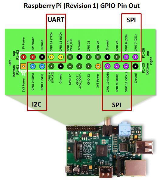
Introduction to the Raspberry Pi GPIO and Physical Computing Circuit Diagram The website pinout.xyz is useful for looking up these kinds of diagrams. It gives you the exact layout and role of each pin. I also have a dedicated article to the Raspberry Pi Pico pinout if you're using this model.. If your breadboard or GPIO kit didn't come with one, I recommend printing this image out.
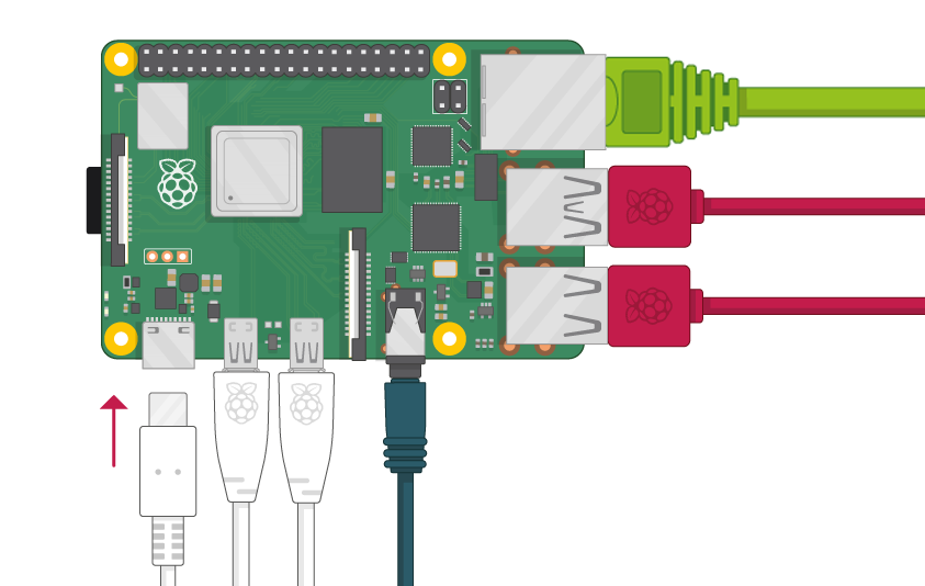
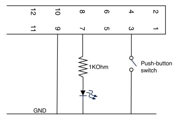
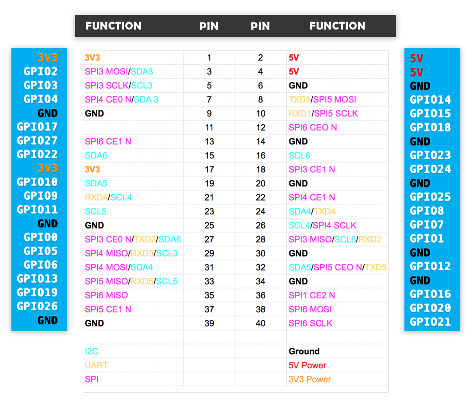
Note that GPIO_2 and GPIO_3 each have a 1800 ohm resistor pull-up to +3.3V fitted on the RPi PCB, which makes these pins unsuitable for these recommended safe switch circuits. To use GPIO_2 or GPIO_3 for a switch input: connect the switch with 220 ohms in series to 0V only , but avoid using them except as a last resort (they are designated for And to compare, here is the Raspberry Pi pinout (for more info, here is a complete guide about Raspberry Pi 4, 3B, 3B+ pinout): The table you see with gpio readall is quite complete, it gives you a lot of useful information. The table is separated into 2 parts, which are mirrored, exactly as the Raspberry Pi pinout overview on the second image.
Introduction to GPIO Pins and WiringPi for Raspberry Pi Circuit Diagram
Support: WiringPi supports all Raspberry Pi Boards including Pi 5 ( 🚧 On the Pi 5, only the GCLK functionality is currently not supported due to missing documentation of the RP1 chip). High Performance: By directly accessing the hardware registers, WiringPi ensures minimal latency and maximum performance for your GPIO operations. Pinout! The Raspberry Pi GPIO pinout guide. This GPIO Pinout is an interactive reference to the Raspberry Pi GPIO pins, and a guide to the Raspberry Pi's GPIO interfaces. Pinout also includes hundreds of pinouts for Raspberry Pi add-on boards, HATs and pHATs. Support Pinout.xyz. If you love Pinout, please help me fund new features and improvements:
The GPIO pins, found on each Raspberry Pi, are one of the best features to expand the device's capabilities. On a Raspberry Pi, the GPIO pinout refers to the map of pins on the board that can be used to connect and control external devices. Each pin can be set as an input or output, allowing interaction with various sensors and accessories.
Raspberry Pi Documentation Circuit Diagram
The image below shows the GPIO pin layout for the Raspberry Pi B+. We can see the red and orange pins can be used to provide power, and the brown act as grounds. The green pins can be configured